Currently Empty: $0.00
Mini Excavator Horsepower and Hydraulic Flow: How They Work Together
Mini excavator specification sheets are full of numbers, and engine horsepower usually sits near the top. It's easy to assume that a higher horsepower figure means a faster, stronger machine. In practice, the engine is only the starting point. It drives a hydraulic pump, and that pump turns mechanical power into the flow and pressure that move the boom, arm, bucket, swing, and tracks. How well these systems are matched has a far greater effect on day-to-day productivity than any single figure on its own.
Horsepower, flow, and pressure each do a different job. Horsepower supplies the energy. Flow sets how quickly the hydraulic functions move. Pressure produces the force that lets the bucket break out hard ground and the boom lifts heavy loads. A machine with plenty of engine power but limited pump flow can feel slow. A machine with high flow but poorly managed power can bog down when the operator digs and swings at the same time. The pump type, control valves, and electronic power management decide how these elements share the available energy.
For contractors and buyers, understanding these relationships leads to better decisions. It helps you compare machines on a fair basis, choose attachments that will actually perform, and spot the difference between a spec sheet that looks strong and a machine that works well on site. The sections below explain how engine power becomes hydraulic power, what flow and pressure each contribute, how manufacturers balance engine output against pump demand, and how to match hydraulic output to the attachments you plan to run.
How Engine Horsepower Supplies Hydraulic Power
On a mini excavator, almost every working function is hydraulic. The engine doesn't move the boom or tracks directly. It turns the hydraulic pump, and the pump pushes oil through control valves to the cylinders and motors that do the work. Engine horsepower is therefore the energy budget for the entire hydraulic system.
Emissions regulations also influence engine choice in this class. Manufacturers often select engine ratings to fit specific emissions thresholds, which is one reason machines of similar size can carry quite different horsepower figures. A lower rating doesn't necessarily mean weaker performance if the hydraulic system makes good use of the power available.
Key takeaway: Engine horsepower is the energy supply for the hydraulic pump, and because hydraulic power equals flow multiplied by pressure, buyers should compare engine output alongside pump flow, relief pressure, and torque rather than on its own.
What Hydraulic Flow Means for Excavator Functions
Hydraulic flow is the volume of oil the pump delivers over time, typically measured in gallons per minute (gpm) or liters per minute (L/min). Flow controls speed. The more oil that reaches a cylinder or motor, the faster it moves, within the limits of the component's size and the system's design.
The relationship is straightforward for a cylinder. Its extension speed depends on how much oil enters it relative to the area of its piston. Doubling the flow into the same cylinder roughly doubles its speed. Putting the same flow into a larger cylinder produces slower movement, because more oil is needed to fill it. This is why cylinder sizing is a balancing act for designers: larger cylinders deliver more force but need more flow to move at the same speed.
Many mini excavators use more than one pump or a split pump that supplies separate circuits. This lets different functions draw from dedicated flow sources, which improves smoothness when several controls are used at once. Some machines combine pump outputs for faster boom or arm movement, then split them again when the operator adds swing or travel.
Flow isn't the same as force. A machine with high flow can move quickly through light work but may slow sharply when it meets hard ground, because the pump control reduces flow as pressure climbs. Published flow figures usually represent maximum output at rated engine speed with little resistance, not what's available during heavy digging. A hands-on test in representative conditions shows how speed holds up under load.
Key takeaway: Hydraulic flow sets how fast cylinders and motors move, so it shapes cycle times, but published maximum flow figures should be read alongside cylinder size, pump arrangement, and real working conditions.
How Pressure Contributes to Digging and Lifting Force
If flow controls speed, pressure controls force. Hydraulic pressure acting on a cylinder's piston produces a pushing or pulling force, and that force moves the boom, arm, and bucket through the excavator's linkage.
Cylinder force is only the beginning. That force travels through pins, levers, and linkages before it reaches the bucket teeth, and the linkage geometry changes the result considerably. This is why manufacturers publish two separate digging figures:
- Bucket digging force: Generated by the bucket cylinder curling the bucket. It's typically the higher figure and matters most for breaking out compacted soil.
- Arm digging force: Generated by the arm cylinder pulling the arm toward the machine. It matters for pulling the bucket through the cut, particularly in trenching.
Both figures vary with working position. Force at the bucket changes as the arm extends, the boom raises, and the bucket rotates. Published values are measured at defined positions, so check how they were determined before comparing machines.
Pressure also drives the swing and travel motors, producing the torque that rotates the upper structure and pushes the tracks against resistance. Lifting capacity depends on hydraulic force too, but it's also limited by stability. On most mini excavators, rated lift capacity in many positions is determined by tipping, not by hydraulic strength. Always use the manufacturer's lift chart for the exact configuration.
Relief valves cap system pressure to protect hoses, seals, pumps, and cylinders. These settings are part of the machine's design and must never be raised beyond the manufacturer's specification. Higher pressure than the system was built for can cause hose bursts, seal failures, and serious injury.
Key takeaway: Pressure acting on cylinder area produces force, but linkage geometry, working position, and stability decide what reaches the bucket, so compare published digging forces and lift charts rather than estimating strength from horsepower or flow.
Balancing Engine Output and Pump Demand
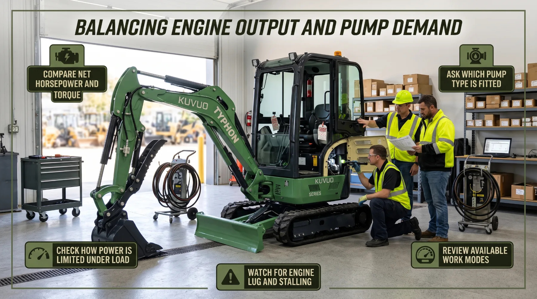
The engine and pump must be matched carefully. If the pump demands more power than the engine can deliver, engine speed falls, response becomes sluggish, and in the worst case the engine stalls. If the pump draws far less than the engine can supply, available power goes unused. Good design keeps hydraulic demand close to, but not beyond, what the engine can sustain.
Pump type plays a large role in how this balance is achieved:
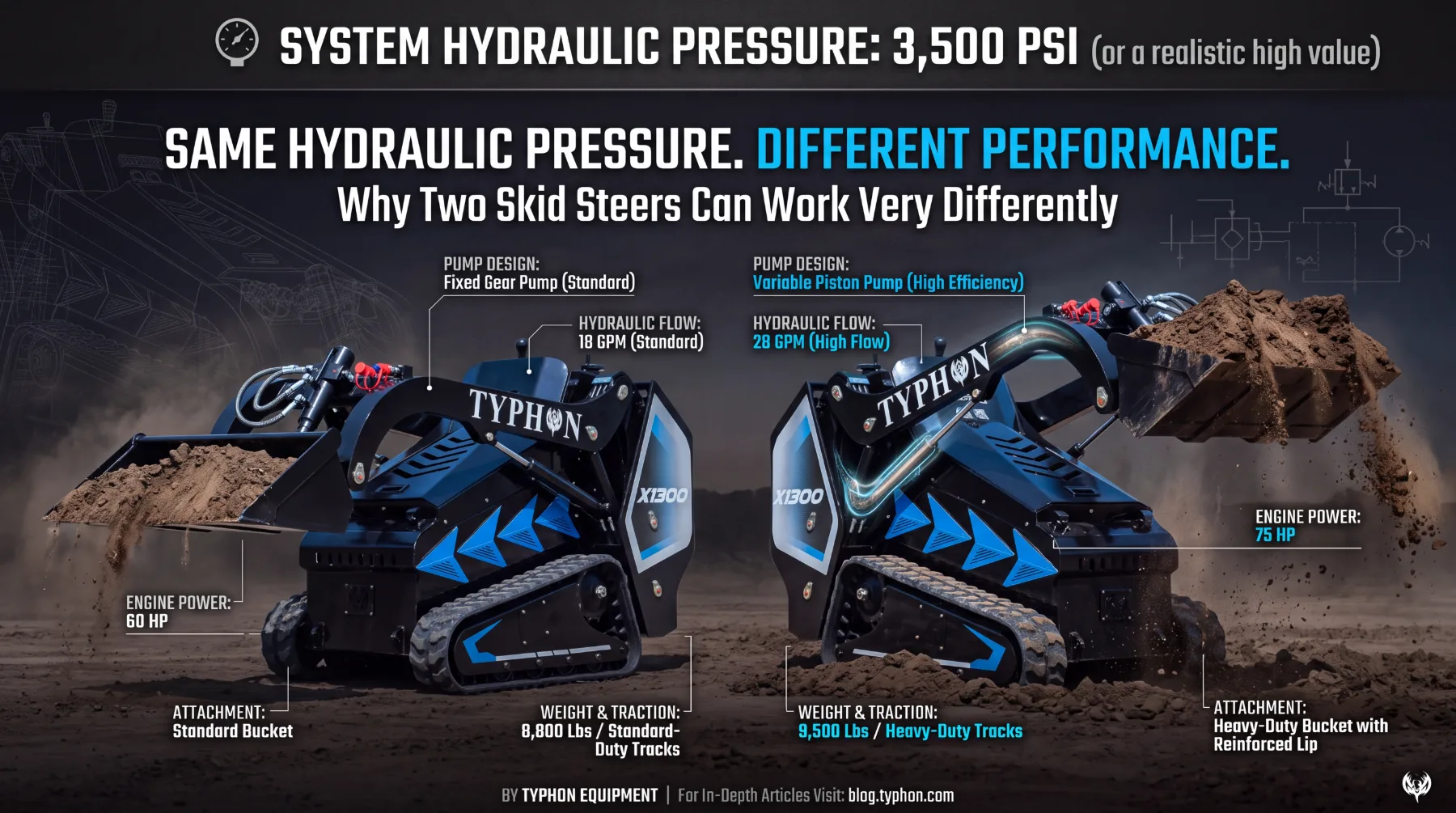
- Fixed-displacement gear pumps: Deliver a set volume of oil per revolution. They're simple and durable, and they're common on smaller or more basic machines. Because their flow doesn't change with load, excess flow is often sent over a relief valve, which turns energy into heat.
- Variable-displacement piston pumps: Adjust how much oil they deliver per revolution. As pressure rises, the pump reduces displacement so total power demand stays within limits. This is often called horsepower or torque control.
- Load-sensing systems: Monitor the pressure each function actually needs and supply only the flow and pressure required. This reduces wasted energy and heat and gives operators finer control.
Electronic engine and pump management takes this further on many modern machines. Controllers monitor engine speed and adjust pump output in real time, preventing stalls and keeping the engine in its most effective operating range. Selectable work modes let operators choose between maximum power for heavy digging and economy settings that reduce fuel use for lighter tasks. Auto-idle and auto-deceleration features lower engine speed when the controls are at rest, saving fuel and reducing noise.
For buyers, this means horsepower alone tells you little about how a machine will feel in the cut. Two excavators with identical engine ratings can perform quite differently depending on pump type and control strategy.
Watch for warning signs during a demonstration. Excessive engine lug, black smoke under load, sluggish recovery after a heavy pull, or rapid oil temperature rise may indicate a poorly matched system for your type of work.
Key takeaway: Pump type and power management decide how effectively a mini excavator uses its engine output, so evaluate the hydraulic system design and work modes, not just the horsepower rating.
Combined Movements and Work Cycle Response
Real excavation rarely uses one function at a time. A skilled operator raises the boom while curling the bucket, swings toward the spoil pile while lifting, and lowers the arm while swinging back to the trench. These combined movements are where the hydraulic system is tested hardest, because several functions compete for the same pump flow at once.
A well-designed system feels smooth and predictable. Functions move at proportional speeds, the bucket follows the operator's intended path, and the machine doesn't lurch when an additional control is engaged. A poorly balanced system may stall the boom when swinging begins, slow the arm sharply under load, or make precise grading difficult.
Travel is an often-overlooked part of this balance. Moving the tracks while operating the boom or blade places heavy demand on the system. Some machines handle straight travel with a dedicated valve that keeps both tracks running evenly while other functions operate, which improves control during repositioning and backfilling.
Note how smoothly functions blend, whether the engine holds speed, and how easily you can meter fine movements. Spec sheets show capability. A test shows how that capability translates into everyday work.
Key takeaway: Combined movements reveal how well a mini excavator shares flow and power between functions, so test digging, lifting, swinging, and travel together before judging a machine's real working performance.
Matching Hydraulic Output to Attachments
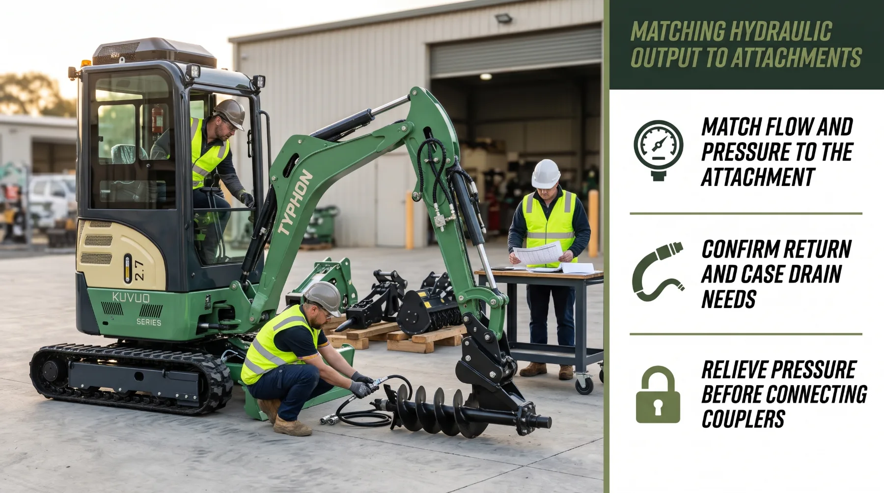
Powered attachments extend what a mini excavator can do, from drilling post holes to breaking concrete to clearing brush. Each attachment is designed to work within a specific hydraulic range, and matching that range to the machine's auxiliary circuit is essential for performance, component life, and safety.
Attachments have different hydraulic demands:
- Augers: Use hydraulic motors that need adequate flow for speed and pressure for torque in hard ground.
- Breakers: Require flow within a defined range and often a low-restriction return directly to the tank. Too much flow can over-speed the breaker and cause damage.
- Grapples and hydraulic thumbs: Rely on cylinders and typically need modest flow with two-way operation.
- Mulchers and brush cutters: Often demand high, continuous flow and may require a case drain line.
- Tilt buckets and tiltrotators: May need dedicated circuits and specific control arrangements.
Check these points before connecting any attachment:
- Flow range: Compare the attachment's required flow with the machine's auxiliary output. Too little flow slows the tool. Too much can overheat it or damage internal components.
- Pressure rating: Confirm the auxiliary relief setting falls within the attachment's approved pressure range.
- One-way or two-way flow: Breakers usually need one-way flow with a direct return, while motors and cylinders may need two-way operation.
- Case drain requirements: Some hydraulic motors need a dedicated low-pressure drain to protect their seals.
- Couplers and hose routing: Use compatible, correctly sized couplers, and never force mismatched fittings together.
- Control arrangement: Confirm the machine has suitable proportional or on/off controls for the tool.
Many modern mini excavators allow auxiliary flow to be adjusted through the display or a valve setting, and some store presets for different attachments. Set flow to the attachment manufacturer's specification each time you change tools.
Safety is critical whenever you connect or disconnect hydraulic attachments. Lower the attachment to the ground, shut down the engine, and relieve pressure in the auxiliary circuit according to the manufacturer's procedure before handling couplers. Never use your hands to check for leaks. Fluid escaping under high pressure can penetrate skin and cause serious injury that needs immediate medical attention. Use cardboard to check suspect fittings, and wear gloves and eye protection.
Key takeaway: Every powered attachment needs a specific flow, pressure, return, and drain arrangement, so confirm the machine's auxiliary circuit matches the attachment's requirements and always relieve pressure before connecting couplers.
Conclusion
Mini excavator performance comes from how the engine and hydraulic system work as one, not from horsepower alone. The engine supplies the energy, flow determines how quickly the boom, arm, bucket, swing, and tracks move, and pressure acting on cylinder area produces the force that reaches the bucket through the linkage. Pump type, load sensing, and electronic power management decide how efficiently that energy is shared, particularly during the combined movements that define real excavation work. Attachments add another layer, since each tool needs its own flow, pressure, and return arrangement to perform reliably and safely. Before your next purchase or rental, review horsepower, pump flow, relief pressure, and digging forces together, ask how the machine manages power under load, and run it through a realistic work cycle with the attachments you plan to use. That approach gives you a clear picture of genuine performance and a machine that delivers dependable results on every job.
Frequently Asked Questions
Does higher horsepower make a mini excavator dig faster?
Not automatically. Horsepower supplies the energy for the hydraulic pump, but digging speed depends on how much flow the pump delivers, how cylinders are sized, how the valves share flow, and how the system manages power under load. A machine with modest horsepower and a well-designed load-sensing system can outperform one with more horsepower and a less efficient setup. Compare pump flow, digging forces, and combined-function response alongside engine output, and test the machine in conditions similar to your own work.
What does hydraulic flow affect?
Hydraulic flow controls the speed of cylinders and motors. It determines how quickly the boom raises, the arm moves, the bucket curls, the upper structure swings, and the tracks travel. Flow also governs how well powered attachments perform, since augers, mulchers, and breakers each need flow within a defined range. Actual speed depends on cylinder size and system design, and published maximum flow is usually measured under light load, so real speed during heavy digging may be lower.
Does hydraulic pressure determine digging force?
Pressure is a major contributor, but it isn't the only factor. Cylinder force equals pressure multiplied by the effective piston area, and that force then passes through the excavator's linkage before reaching the bucket teeth. Linkage geometry, bucket position, and arm position all change the force delivered. That's why manufacturers publish separate bucket and arm digging forces measured at defined positions. Relief pressure settings are fixed by the manufacturer and should never be raised to increase force.
Why should attachment flow requirements be checked?
Each powered attachment is designed for a specific flow and pressure range, and some also need one-way flow, a direct return to tank, or a case drain line. Insufficient flow makes the tool slow and ineffective, while excessive flow or pressure can overheat it, damage seals, or cause motor and housing failures. Incorrect return arrangements can also create back pressure. Confirm the machine's auxiliary output and connections match the attachment manufacturer's requirements, and set auxiliary flow correctly before every use.